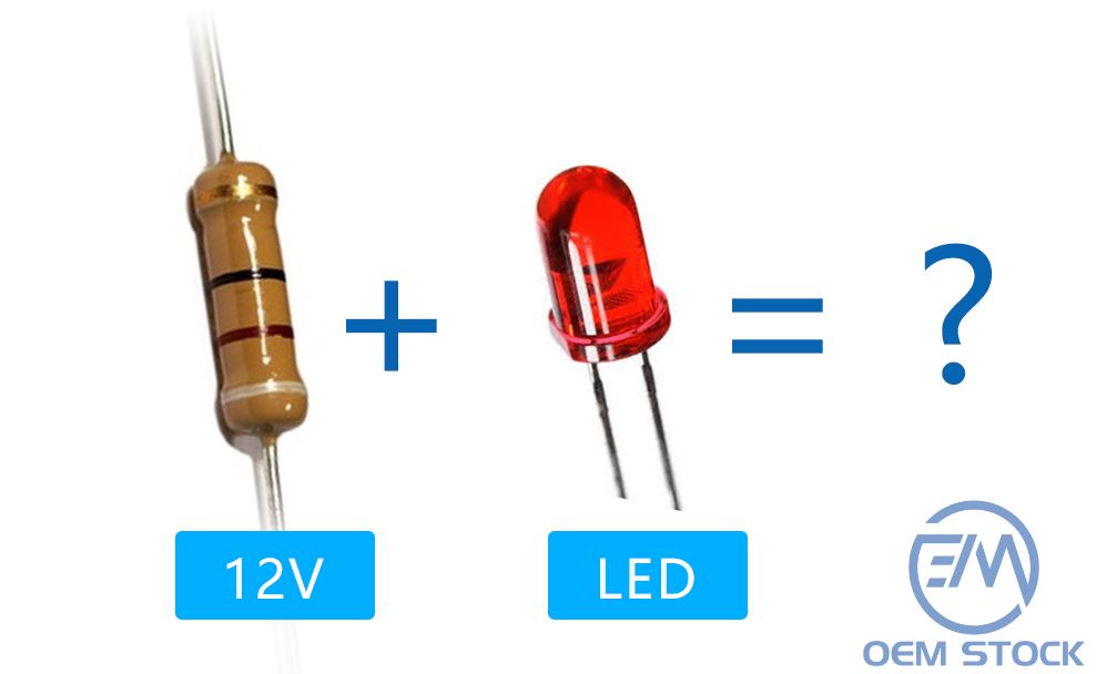
If you power LEDs from a 12V supply, the series resistor is what keeps current under control and your LEDs alive. This expanded guide builds on our previous overview - What Is an LED Resistor and How to Calculate the Right Value - and dives deeper into 12V-specific design choices: step-by-step calculation, how much wattage headroom to use, wiring methods, resistor types, troubleshooting, and advanced options such as PWM dimming and constant-current drivers.

Standard indicator LEDs have a forward voltage Vf of roughly 1.8–2.2 V (red) or ~3.0–3.6 V (white/blue). A 12V source is far above that, so without a resistor the current skyrockets, leading to overheating and instant failure. The series resistor drops the excess voltage and limits current to a safe value (typically 10–20 mA for small discrete LEDs).
1) Voltage across the resistor: Vr = Vs − Vf
2) Resistor value: R = Vr / If
3) Resistor power: P = Vr × If (use margin; see next section)
Example A - Single Red LED @ 20 mA
Vs = 12 V, Vf ≈ 2.0 V → Vr = 10 V → R = 10 / 0.02 = 500 Ω.
Nearest standard value: 510 Ω (slightly less current), or 470 Ω (slightly more current).
Power: P = 10 × 0.02 = 0.20 W.
Example B - Single White LED @ 20 mA
Vs = 12 V, Vf ≈ 3.2 V → Vr = 8.8 V → R = 8.8 / 0.02 = 440 Ω.
Nearest standard: 470 Ω (~18.7 mA) or 430 Ω (~20.5 mA).
Power: P = 8.8 × 0.02 = 0.176 W.
Example C - Three Red LEDs in Series @ 20 mA
Vf_total ≈ 3 × 2.0 = 6.0 V → Vr = 12 − 6 = 6 V → R = 6 / 0.02 = 300 Ω.
Power: P = 6 × 0.02 = 0.12 W.
Tip: Prefer the next higher E12/E24 value if you want a cooler, longer-life setup. If you halve the current (e.g., 10 mA instead of 20 mA), R doubles and P quarters.
After computing P = Vr × If, choose a resistor with headroom. A practical rule is at least 2× the calculated power:
| Type | What It Is | Pros | Cons | Typical Uses |
|---|---|---|---|---|
| Through-Hole (Axial) | Leaded parts for perfboard/hand-solder | Easy to handle, wide wattage range | Bulky; not ideal for compact builds | Prototyping, education, hobby |
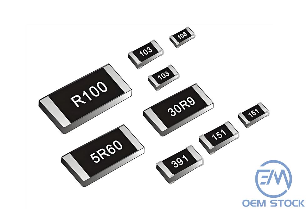
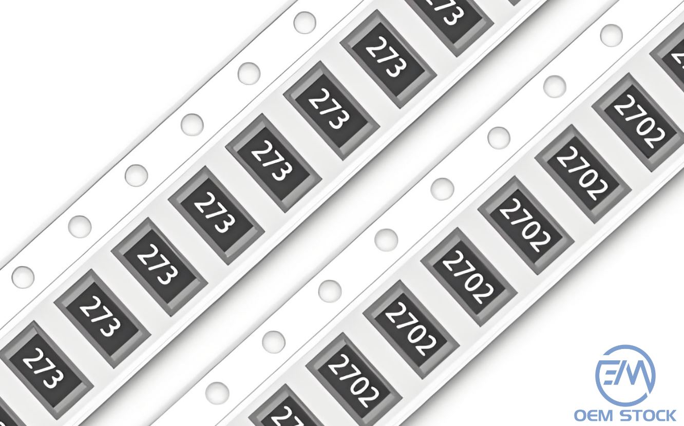
| SMD (Chip Resistors) | Surface-mount, compact footprints | Small size, production-friendly | Harder to hand-solder; wattage limited by size | Commercial products, dense PCBs |
| Wirewound/Power | High-wattage, robust resistors | Excellent heat handling | Larger, costlier | High-power LEDs, automotive loads |
| Pre-wired LED (built-in R) | LED assemblies with internal resistor | Plug-and-play, safer for beginners | Fixed current; less flexible | Indicators, quick installs, signage |
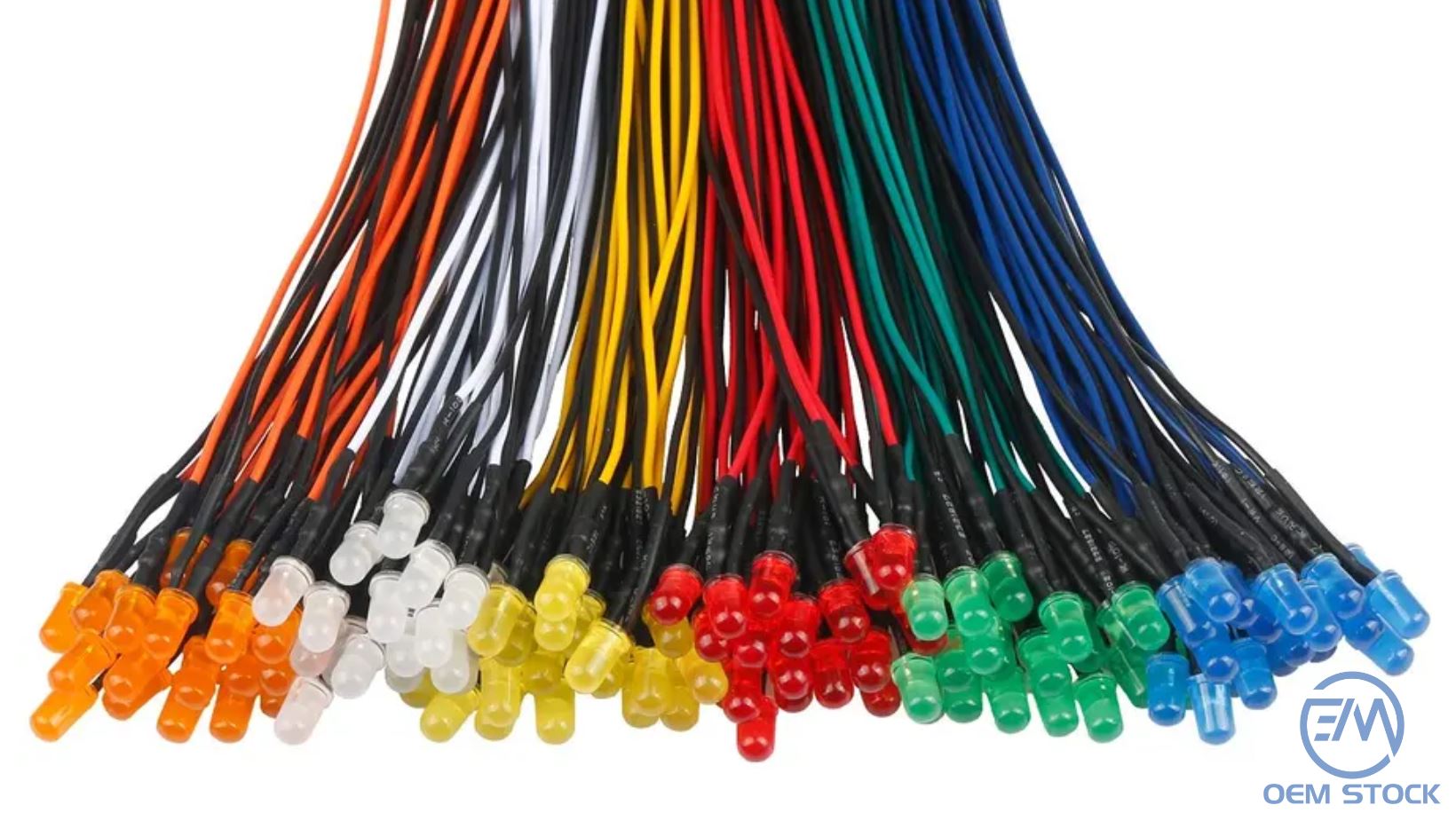
Pre-wired 12V indicators include an internal resistor sized for typical currents. They save time and reduce mistakes, especially in vehicles, panels, and signage. Trade-offs: less freedom to set exact current/brightness, slightly higher cost, and physical size may be larger than a bare LED + resistor.
| Scenario | Assumptions | Result | Suggested Wattage |
|---|---|---|---|
| Single red LED | Vf = 2.0 V, If = 20 mA → Vr = 10 V | R = 500 Ω → use 510 Ω; P = 0.20 W | ≥ 0.5 W |
| Single white LED | Vf = 3.2 V, If = 20 mA → Vr = 8.8 V | R = 440 Ω → use 470 Ω; P = 0.176 W | ≥ 0.5 W |
| Three red in series | Vf_total ≈ 6.0 V, If = 20 mA → Vr = 6.0 V | R = 300 Ω; P = 0.12 W | ≥ 0.25–0.5 W |
| Single white, softer output | Vf = 3.2 V, If = 10 mA → Vr = 8.8 V | R = 880 Ω (use 910 Ω); P = 0.088 W | ≥ 0.25 W |
No. It depends on Vf and desired If. 1 kΩ often gives ~9–10 mA with a red LED on 12 V (Vr≈10 V → I≈10 mA), which may be fine if you want it dimmer. Always compute first.
Yes. The resistor just needs to be in series; electrical behavior is the same either side.
Only if you're trying to mimic the current draw of incandescent bulbs to satisfy a vehicle's detection circuit. For simple LED lighting, you only need the series current-limiting resistor.
For high-power LEDs, long strings, or where supply voltage varies significantly (e.g., vehicles). Drivers regulate current precisely and reduce thermal stress.