In practice, protection components are not designed at their absolute limits. The "correct" part is the one that protects repeatably across manufacturing tolerances, temperature, wiring differences, and real customer behavior (hot-plugging, cable swaps, industrial noise). That is why engineers talk about margins, not just nominal ratings.
Choose VRWM above worst-case steady-state voltage (including tolerance and ripple). Too close causes leakage and unnecessary stress.
Ensure VC at the expected waveform/current stays below IC limits with headroom for layout-induced overshoot.
Expected surge levels should not approach the device rating repeatedly. Harsh environments demand larger power class.
Higher power TVS parts need copper area. Without it, they can run hotter and drift faster under repetitive stress.
Surge ratings are waveform-dependent. Two devices with the same "watts" label may not behave the same under different waveforms. Engineers check the waveform used for IPP/Pppm and match it to the test environment.
| Waveform | Where it appears | Why it matters for selection |
|---|---|---|
| IEC 61000-4-2 (ESD) | User contact, external connectors | Extremely fast edges; layout and parasitics dominate; low inductance return path is critical |
| 8/20µs | General surge events, industrial transients | Common reference for peak current rating; suitable for comparing surge robustness |
| 10/1000µs | Telecom/longer pulses | Longer energy delivery; affects thermal stress and power dissipation |
| ISO 7637 pulses | Automotive transient events | Includes specific pulse shapes; selection may require dedicated automotive-rated parts |
A TVS diode is not an ideal clamp. As surge current rises, the clamp voltage increases. This slope is often explained by dynamic resistance. In simple terms:
Vclamp ≈ Voffset + I × Rdyn
Two TVS parts may show similar VC under one test current, yet behave differently at your real surge current. Engineers compare devices by how quickly clamp voltage rises as current increases-especially when protecting low-voltage ICs.
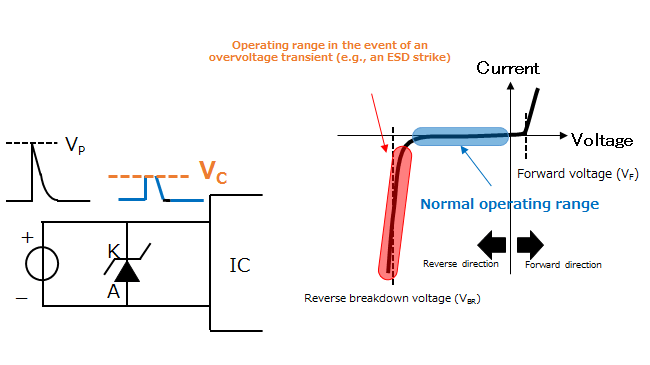
The number one reason "TVS protection didn't work" is that the surge current returns through an inductive path. During fast transients, even small inductance creates significant overshoot:
Vovershoot = L × (di/dt)
TVS diodes can degrade under repetitive surges. Over time, you might see:
A professional protection design includes a clear validation plan and documented test results. Engineers often validate in three layers:
Verify steady-state leakage at max voltage and temperature. Confirm no nuisance conduction.
Test IEC-style ESD points: connector pins, shield, enclosure seams. Watch for resets, latch-up, and errors.
Validate against targeted surge waveforms for your market. Re-check leakage after stress to detect aging.
Q: Why does VC look acceptable but the MCU still resets during ESD?
A: Reset events often come from ground bounce and coupling, not just over-voltage. Improve the return path, connector shield strategy, and keep TVS loops short.
Q: Is higher wattage always better?
A: Not always. Bigger parts can help with energy, but layout and system behavior still dominate. Also consider leakage, size, and cost.
Q: How do I choose between uni and bi-directional TVS?
A: Use unidirectional for DC rails with known polarity; bidirectional for AC or lines that can swing both directions.
 Upload