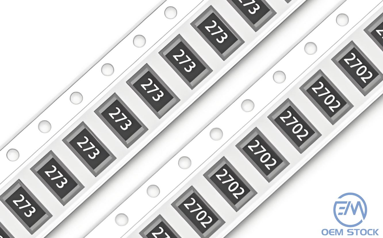
In modern electronics, a 0603 resistor often looks identical regardless of whether it is thick film or thin film. But anyone who has debugged precision analog circuits, noisy sensor outputs or unstable gain networks knows that the underlying technology makes a dramatic difference. This guide explains thick film vs thin film resistors from an engineer's real-world perspective-how they behave, when they fail, and why selecting the correct type can save weeks of troubleshooting.
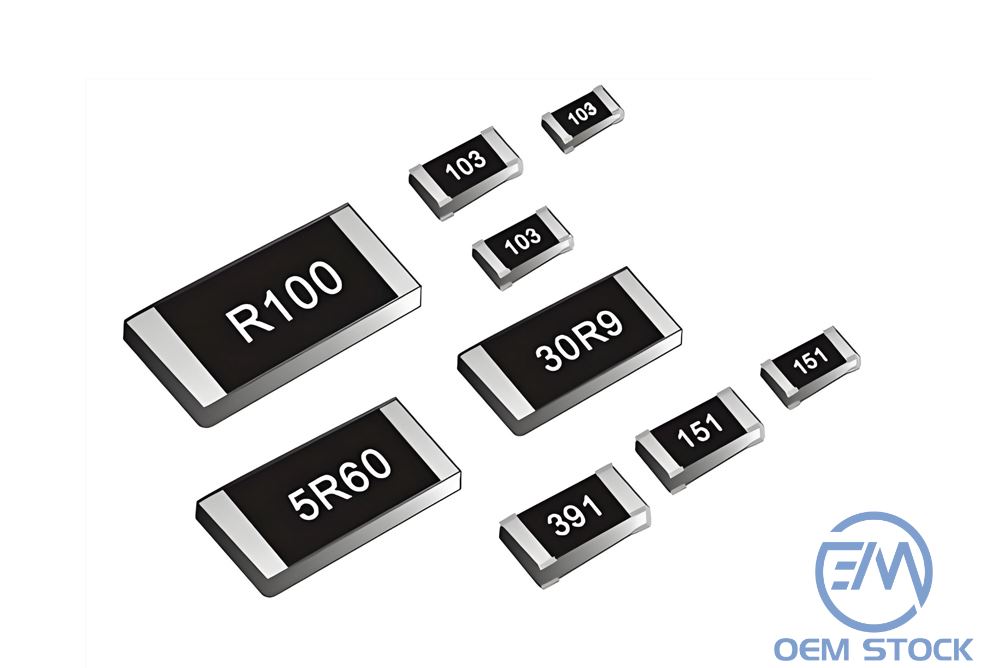
Thick film SMD resistors are manufactured by printing a resistive paste (usually a metal-oxide composite) onto a ceramic substrate and firing it at high temperature. The resulting film is relatively thick-on the order of tens of micrometers. This process is inexpensive and robust, which is why thick film resistors dominate consumer electronics and digital boards.
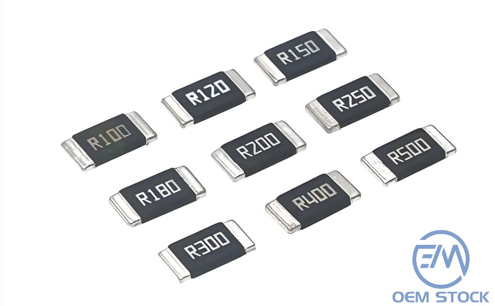
Thin film resistors use a vacuum sputtering process to deposit an ultra-thin metal layer-typically tens to hundreds of nanometers- onto the substrate. This controlled, uniform film structure gives thin film resistors their signature characteristics: low noise, high linearity and exceptional stability.
Datasheets often list tolerance and TCR, but engineers who build precision hardware know additional factors matter just as much.
| Parameter | Thick Film | Thin Film |
|---|---|---|
| Noise | Higher 1/f and excess noise | Very low noise, suitable for instrumentation |
| Tolerance | 1%–5% | 0.1%–1% |
| TCR (Temperature Coefficient) | 100–200 ppm/°C | 5–25 ppm/°C |
| Voltage Coefficient | Noticeable non-linearity | Minimal; excellent linearity |
| Long-Term Drift | Moderate | Very low; excellent stability |
| Pulse/Surge Handling | Generally good | Often weaker unless rated |
| Cost | Very low | Higher (but still cheap overall) |
Noise isn't just a theoretical concept-it shows up on the oscilloscope. Thick film resistors have higher excess noise because of their granular conductive structure. This noise becomes visible in:
Thin film resistors, with their uniform sputtered metal layer, have far less noise. If your design involves measuring microvolts or microamps, thin film resistors are not optional-they are mandatory.
Thick film resistors can change value significantly with temperature. A TCR of 200 ppm/°C means a 10 kΩ resistor can drift ±200 ohms for every 10 °C. For high-accuracy circuits, this drift makes calibration nearly impossible.
Thin film resistors, at 5–25 ppm/°C, remain stable even when environmental temperature changes rapidly. Their linearity also ensures predictable behavior across voltage and current swings-critical for:
One area where thick film resistors outperform thin film is surge handling. The printed resistive layer is physically thicker and can absorb brief but intense energy bursts:
Thin film parts are not designed for punishment. Unless explicitly surge-rated, they are best kept in stable, low-stress analog environments.
Thick film resistors are extremely cheap-fractions of a cent at scale. Thin film resistors cost more, but still represent a tiny fraction of the BOM. What you gain is far more valuable:
In products where precision matters, the cost difference is negligible compared with the engineering time saved debugging drift or noise problems.
Based on extensive real-world usage, here are the practical rules engineers rely on:
Thick film resistors are excellent for general-purpose electronics, offering robust performance at very low cost. But for precision circuits-where noise, drift, temperature stability and linearity matter-thin film resistors are simply the correct choice.
In professional engineering work, the difference is not theoretical. It is measurable, repeatable, and often critical to passing validation. Understanding these real-world distinctions helps ensure your circuit performs as designed-not just on day one, but years into the product's lifetime.
 Upload