If you have ever troubleshot a drifting measurement circuit, noisy sensor interface, or an overheating power board, you probably discovered-sometimes the hard way-that a resistor is rarely just "a resistor." This guide is written from an engineering perspective based on real design work, failure analysis, and field experience across industrial, consumer, medical, and automotive electronics.
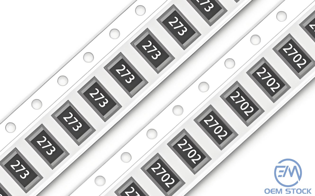
Rather than repeating textbook definitions, this article explains how resistors behave in real hardware, why certain types fail, and how to select parts that will survive the environments they operate in.
On schematics, resistors are small, cheap, and often overlooked. But on the bench, their characteristics can determine whether a product meets noise specifications, passes EMC tests, or remains within calibration after years of use.
In practice, every resistor has:
Ignoring these real-world behaviors is one of the most common causes of subtle circuit problems.
Below is a practical overview of the resistor technologies you'll encounter in modern designs, along with typical usage scenarios based on what actually works in the field.
Carbon film resistors have existed for decades. They are inexpensive and adequate for non-critical consumer electronics. But they exhibit higher noise, weaker stability, and larger drift over time. They are rarely used in precision or industrial designs today.
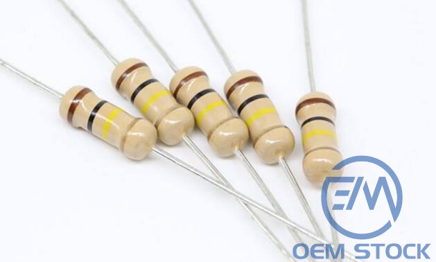
Metal film resistors are the "go-to" choice for precision through-hole circuits. They offer:

You'll find them in audio equipment, measurement tools, and analog instrumentation.
The most common type in mass production. They are:
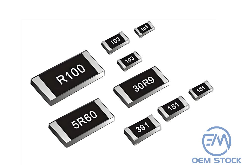
But they suffer from higher noise, higher TCR, and worse linearity. Not recommended for high-accuracy analog.
Thin film resistors are engineered for precision and stability. They provide:
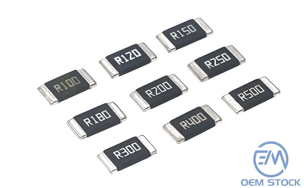
They are essential for:
Wirewound resistors handle:
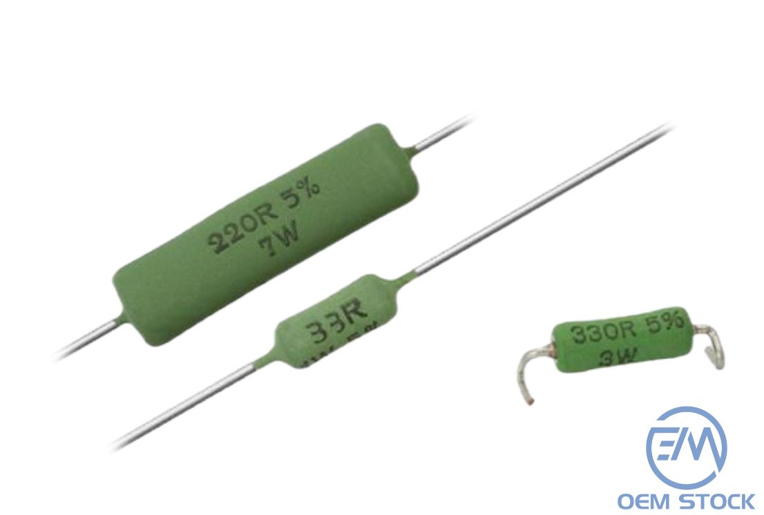
They are inductive by nature and not suitable for RF or fast switching.
Many beginners focus only on tolerance (e.g., 1% vs 5%). Professionals know tolerance is only the starting point.
Three factors matter far more in precision circuits:
A resistor with 200 ppm/°C TCR can drift significantly in environments with wide temperature swings. Thin film (±10 ppm/°C) is preferred for stable gain networks.
High VCR results in non-linearity, especially noticeable in audio and instrumentation amplifiers. Thin film parts have far lower VCR than thick film.
Humidity, heat, and mechanical stress cause gradual resistance changes. Metal film and thin film resistors exhibit the best long-term stability.
A resistor's power rating assumes:
In real products-especially compact modern enclosures-conditions vary drastically. A "0.25 W resistor" may be safe only at 0.12 W in a sealed box.
Good engineers run resistors at 25–50% of their rated power.
Startup inrush or motor braking can destroy a resistor even if its average power is low. For these conditions, surge-rated or wirewound parts should be used.
Based on years of design, test, and failure analysis, these guidelines hold true:
Usually caused by overheating, excessive pulse load, or cracked solder joints.
Often seen in thick film resistors operating in high humidity or elevated temperature environments.
Damaged or low-quality resistors introduce broadband or 1/f noise into sensitive circuits.
A clear sign that the resistor was operating too close to its power limit.
Choosing the right resistor may seem trivial, but it greatly influences the performance and reliability of a product. The best engineers learn to treat resistors as engineered devices, not placeholders. A few smart decisions-such as using thin film instead of thick film in gain networks, or derating power more conservatively-can remove entire classes of failure.
In 2025, with higher-density designs and tighter EMC requirements, understanding real resistor behavior is more important than ever.
 Upload