Resistors sit alongside inductors and capacitors as the three fundamental passive components.
In practical design, the resistor is the energy dissipator-it turns electrical energy into heat.
That "loss" is not a bug: it's how we shape voltages, limit current, bias amplifiers, sense power, and tame fast edges.
Design mindset: A "good" resistor is not always low-loss. It's the right value, package, stability, and predictable behavior across temperature, voltage, and frequency. Predictability beats perfection.
Digital boards: pull-ups/downs, source termination, strap options, 0-Ω jumpers.
Analog/RF: gain setting, bias networks, filters, precision dividers, noise shaping.
Power: current sense, inrush limiting, bleeders, snubbers, preheat/heating elements.
Resistors control current, shape voltages, absorb energy, and stabilize systems.
2. Ohm's Law & Joule's Law (Engineer's Cheatsheet)
Two equations frame almost every resistor decision:
Ohm's Law:V = I · R → Set R to get the current you want for a given V.
Joule's Law (power):P = I² · R = V² / R → Always check P against package rating and thermal rise.
When you choose a value, you're implicitly choosing a power dissipation at a target operating point.
In precision designs, add margin: run resistors at 50–70% of rated power under worst-case conditions.
Quick sanity checks:
Current-limiter: If LED drop is 2.0 V on a 5.0 V rail at 10 mA, R ≈ (5−2)/0.01 = 300 Ω; power ≈ 0.03 W → 0603 is fine.
Bleeder: 48 V rail, 100 kΩ bleeder → I ≈ 0.48 mA, P ≈ 23 mW.
Divider loading: Choose divider current 50–100× higher than the load input bias for accuracy.
3. Real-World Equivalent Model (R + L + C)
No physical resistor is "pure R." Every part includes a small series inductance (L) and a shunt capacitance (C).
At DC that's irrelevant; at RF it defines where your "resistor" stops behaving like a resistor.
Equivalent model (illustrative). Real resistors are R in series with a tiny L, shunted by a tiny C.
3.1 Where do the parasitics come from?
Series L: terminations, package leads, internal spiral trims (film parts) - typically a few nH.
Shunt C: electrode overlap and dielectric path between terminals - typically a few pF (thick film) down to sub-pF (thin/foil).
3.2 What's a "good" value for L and C?
As a practical rule:
Thick-film 0402/0603: L ~ 1–3 nH, C ~ 0.5–3 pF (ballpark).
Thin-film precision: L often sub-nH, C down to ~0.05–0.2 pF for small sizes.
Foil/optimized RF parts: the best parts push parasitics even lower; specific datasheets vary.
3.3 Why the resistor value matters at RF
For small R, series L dominates sooner (inductive behavior); for large R, shunt C dominates sooner (capacitive behavior).
This is why a 75 Ω thin-film part can stay resistive deep into GHz while a 10 kΩ thick-film can "look" capacitive by a few hundred MHz.
4. High-Frequency Behavior: What Actually Breaks First
4.1 Self-resonance and impedance drift
Combine L and C with the nominal R and you'll hit a self-resonant frequency (SRF), above which the part's impedance
diverges from the DC value. Around SRF, the resistor's impedance magnitude can dip or rise depending on R, L, and C.
4.2 Package and layout effects
Package: Smaller packages (0402 vs 0603) generally reduce L and C, pushing usable frequency higher.
Footprint: Shorter pads and tighter loop area lower series inductance.
Planes nearby: More plane overlap increases shunt capacitance; control stackup to manage C.
4.3 Film type differences
Thick film: cost-effective, but higher parasitics and excess noise; good to hundreds of MHz.
Thin film: lower noise, tighter TCR, lower parasitics; strong up to multi-GHz for certain values.
Metal foil: state-of-the-art stability and low parasitics; premium cost.
RF sanity tips:
For source termination on ~50 Ω lines, start with 22–33 Ω near the driver pin and tune on the scope.
Prefer thin-film for gain-setting and precision dividers in high-speed ADC/DAC front-ends.
On GHz paths, minimize pad/trace stubs; consider resistor arrays only if placement doesn't introduce extra loop area.
Illustrative comparison: thin-film keeps "resistive" behavior farther into GHz for mid-range values.
5. E-Series Standard Values (IEC Preferred Numbers)
Resistor values follow ISO/IEC preferred number series. Within each decade (1–10, 10–100, …) the values form a near-geometric progression with common ratio 10^(1/N), where N is the count of steps per decade.
Series
Values/Decade (N)
Typical Tolerance
Common Ratio
E12
12
±10%
10^(1/12)
E24
24
±5%, ±2%
10^(1/24)
E48
48
±2%
10^(1/48)
E96
96
±1%
10^(1/96)
E192
192
±0.5%, ±0.25%, ±0.1%
10^(1/192)
5.1 Memory Tricks
The number in the series name is the count of values per decade (e.g., E24 → 24 values).
Multiply/divide any base value by powers of 10 to cover other decades (e.g., 4.7 → 47, 470, 4.7k, 47k…).
Higher series (E96/E192) = tighter spacing = supports tighter tolerance.
E96/E192 add many midpoints between E24 values for precision designs. Vendors often provide a full table; in practice you'll select values from part search filters and verify availability/tolerance/TCR.
Illustrative spacing of E12/E24/E96 (insert your chart asset here).
6. Marking Systems for SMD & Axial Resistors
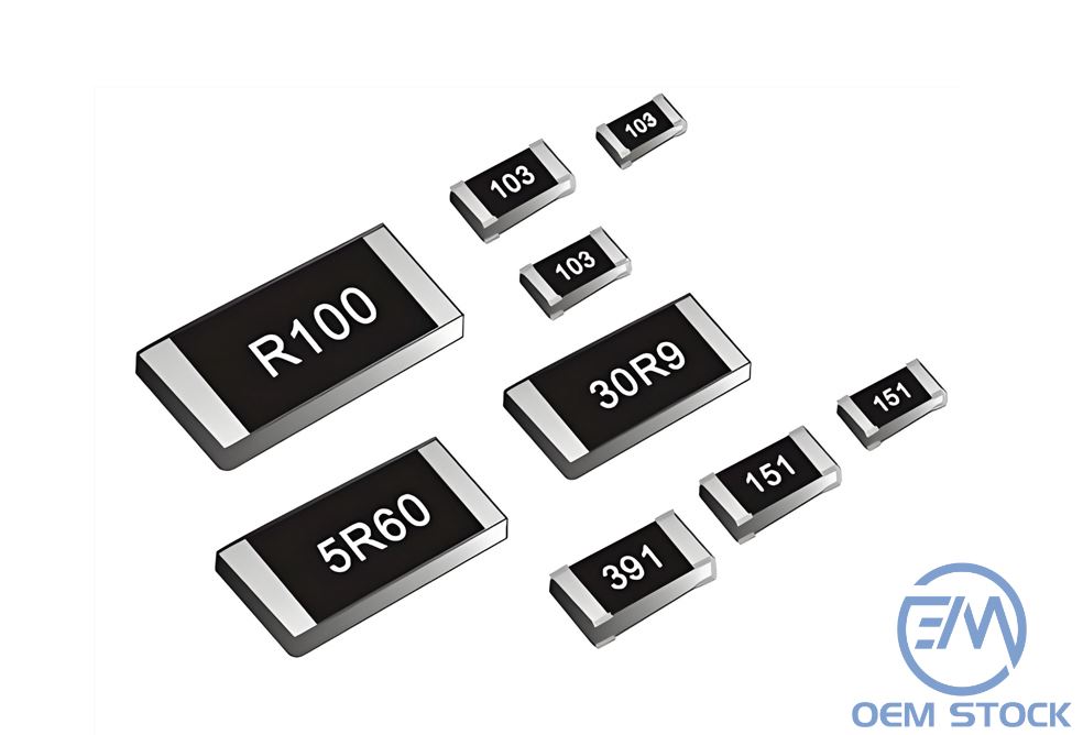
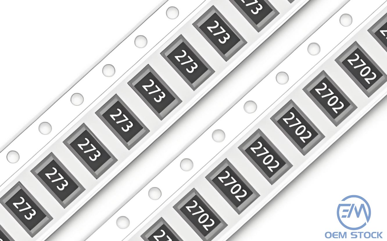
6.1 SMD Numeric Codes (E12/E24 & General)
3-digit code (≥10 Ω): first two digits = significant figures; third = power of ten.
Examples: 472 → 4.7 kΩ, 100 → 10 Ω.
4-digit code: first three digits = significant figures; fourth = power of ten.
Example: 1002 → 10.0 kΩ.
0-ohm jumpers: often marked 0 or 000.
6.2 EIA-96 Code (for 1% resistors)
EIA-96 uses two digits + one letter. The two digits are an index (01–96) into the E96 table; the letter is the decade multiplier:
Letter
×10ⁿ
Letter
×10ⁿ
Y
10−1
A
10+1
X
100
B
10+2
C
10+3
D
10+4
Example:47C → index 47 in E96 table = 30.1; C = ×103 ⇒ 30.1 kΩ.
6.3 Tolerance & TCR Letters (Common)
Tolerance: F = ±1%, G = ±2%, J = ±5%, K = ±10%, M = ±20%.
TCR (ppm/°C): e.g., B = 10, C = 15, D = 25, E = 50, F = 100 (vendor-specific; always check datasheet).
7. Axial Color Bands (4-Band / 5-Band)
Read from the tolerance end (usually gold/silver is on the right). For 4-band: digit-digit-multiplier-tolerance. For 5-band: digit-digit-digit-multiplier-tolerance.
Color bands: digits → multiplier → tolerance (→ optional tempco).
7.3 Color Reference Table
Color
Digit
Multiplier
Tolerance
Tempco (ppm/°C)
Black
0
×100
-
250
Brown
1
×101
±1%
100
Red
2
×102
±2%
50
Orange
3
×103
-
15
Yellow
4
×104
-
25
Green
5
×105
±0.5%
-
Blue
6
×106
±0.25%
-
Violet
7
×107
±0.1%
-
Gray
8
×108
±0.05%
-
White
9
×109
-
-
Gold
-
×10−1
±5%
-
Silver
-
×10−2
±10%
-
No band
-
-
±20%
-
Pro tip: Many modern high-precision parts are laser-trimmed thin film and may ship as SMD without color bands; always rely on reel/label/datasheet for definitive value and tolerance.
8. Types & Manufacturing Process (What's Inside Your Resistor)
Different constructions yield very different electrical behaviors: noise, TCR, parasitics, surge handling, and long-term stability.
This section tours the major families used on real boards. (Variable and sensing parts will be covered in the next section.)
8.1 Axial Leaded (Through-Hole)
Wirewound Resistors
A nickel-chromium (NiCr) alloy wire is wound on a ceramic core; resistance is set by wire gauge and turns.
Wirewounds can be extremely precise and handle high power when combined with heatsinking.
Cons: premium price; limited availability/values compared to thick film volume parts.
Use when: metrology-grade measurements, precision references, top-tier instrumentation.
Current Sense (Low-ohm Shunts)
Designed to measure current via small voltage drop (V = I·R). Often metal-element or foil with Kelvin terminations.
Pros: low resistance (mΩ), high pulse and power handling; 4-terminal options reduce lead error.
Cons: layout sensitive (heat spreading, copper width); need to budget sense amp common-mode range.
Use when: DC/DC converters, battery packs, motor drivers, power rails.
8.3 What Spiral Trimming Does (and Why You Care)
Film resistors are typically laser-trimmed in a spiral pattern to raise resistance. The spiral adds some series inductance and introduces
slight non-linearity at very high frequencies. For RF or ultra-fast edges, prefer parts designed with minimized trim length or use foil types.
8.4 Package, Pads, and Parasitics
Smaller case = usually lower L/C, higher usable frequency, but lower power rating.
Pad geometry = shorter pads and tighter loop area reduce inductance; excessive plane overlap increases shunt capacitance.
Arrays = great for density, but shared substrate/coupling can matter in precision or RF paths.
8.5 Quick Comparison (At a Glance)
Type
Noise
TCR
Parasitics @ HF
Pulse/Power
Stability
Cost
Best For
Thick Film (SMD)
Higher
Fair
Higher
Fair
Fair
Lowest
General digital, pull-ups/downs
Thin Film (SMD)
Low
Good–Excellent
Low
Fair–Good
Good
Medium
Precision analog, HF dividers, gain set
Metal Foil
Lowest
Excellent
Lowest
Good
Excellent
High
Metrology, references, top-tier instrumentation
Wirewound (Axial)
Very Low
Excellent
Poor (inductive)
Excellent
Excellent
Medium
High power/energy, precision shunt (low HF)
Metal Film (Axial)
Low
Good–Excellent
Moderate
Good
Good–Excellent
Medium
Precision through-hole analog
Metal Oxide Film (Axial)
Med
Good
Moderate
Good–Excellent
Good
Low–Med
High temp, industrial/power
Carbon Film (Axial)
Med–High
Med
Moderate
Med
Med
Low
General through-hole where cost wins
Carbon Composition
High
Poor
Moderate
Good (pulses)
Poor–Med
Low
Legacy, special pulse apps
Current Sense (Shunt)
Low
Good
Low
Excellent
Good
Med
Power rails, motor control, battery packs
Engineer's rule-of-thumb: For anything that touches precision analog or RF front-ends, default to thin film unless there's a clear reason not to
(power, surge, budget). For everything else, thick film is usually fine and cost-effective.
9. Variable & Sensing Resistors
9.1 Adjustable Resistors
Potentiometer (3-terminal divider)
A potentiometer splits an end-to-end resistance into two parts via a wiper. Use it as a divider for adjustable voltage.
Derate to ~50–70% of rated power under worst-case ambient.
Distribute power across series/parallel elements for heat spreading.
11.3 Pulses & Surge
Check vendor pulse rating curves (single pulse, repetitive). For surge protection, coordinate MOV/MLV with series impedance and TVS.
11.4 Divider Error Budget
For Vout = Vin · R2 / (R1 + R2), include tolerance, TCR mismatch, input bias loading, and ADC source impedance requirements. Use thin-film matched pairs for precision.
11.5 Matching for High-Speed
Estimate series resistor as R ≈ Z0 − R_driver. Validate on scope; look at overshoot/ringing and eye diagrams where applicable.
Default choices that age well: Thin-film for precision/HF; thick-film for general pulls and options; foil for ultra-stable references; wirewound for high power/energy.
12. FAQs
Q1. Thick film vs thin film-when to choose which?
Thick film is economical and fine for most digital/general circuits. Thin film (or foil) provides lower noise, tighter TCR, and smaller parasitics-ideal for precision analog and HF.
Q2. How much current can a 0-Ω resistor carry?
Datasheet-specific. As a rough guide, 0402 0 Ω is often ≤50 mΩ and ~1 A. Verify P = I²R, temperature rise, and consider bigger packages or parallel parts.
Q3. What value for source termination?
Start with Z0 − R_driver (e.g., 50 Ω line, ~20 Ω driver → ~30 Ω) and fine-tune on the scope.
Q4. PTC vs fuse?
PTC self-resets and suits brief over-currents but has leakage when tripped. Fuses are one-time and isolate nearly completely.
Q5. Is one MOV enough for surge?
Often not. Use MOV → series impedance → TVS to keep residual voltage within IC limits.
Q6. Do color bands still matter?
For SMD, numeric/EIA-96 codes dominate. Axial through-hole still uses color bands; always confirm with labels/datasheets for precision builds.