Capacitor Bypass: What It IsAndWhy It Matters In Electronics
When working with or troubleshooting electronics, you're bound to see that components are often described as being "capacitor coupled," "capacitor bypassed," and so on. To those new to electronics this may sound like a complex idea, but in fact is one of the basic fundamentals to assure circuit performance. In this article, we shall learn details about a bypass capacitor: what they are, why we need them, how they work, and how to select them.
What Is a Bypass Capacitor?
A bypass capacitor is a tiny capacitorconnectedbetween a power supply line and ground.It is usedprimarilyas a low-impedance path for high-frequency noise andcrosstalk,essentially"short-circuiting"undesirableAC signals to ground, all the whilepermittingDC to passunimpeded.
Listen, it isbasicallylike a short-term energy storagesystemwhichkeeps your circuit stable whenever there are voltage fluctuations.Thatmeansthe bypass capacitor helps "smooth out" the supply by filtering noise so thatdelicatecomponents, such as microcontrollers, amplifiers, and digital ICs, canbeassuredof a clean power supply.
Why would You Need a Capacitor Bypass?
Analog Circuits would go haywire with out the use of bypass-capacitors.True! Here are the underlying reasons why bypass caps are required:
Noise Reduction
Power supply lines can be affected by unwanted high-frequency noise from switching regulators, digital activity or external sources of electromagnetic interference. Such noise is filtered by bypass capacitor by shunting the noise to ground.
Protection Against Voltage Spikes
They also serve to soak up momentary voltage spikes that would otherwise toast sensitive parts.
In a nutshell, the use of a
capacitor bypass results in better performance, more stable signals and longer component life.
How Does a Bypass CapacitorFunction?
Rule of thumb to Remember How Do Bypass Capacitors Work, keep this rule in mind:
Capacitors don't like to change voltage.
If a digital chip suddenly requires more current, the supply voltage will sag. At that moment, the bypass capacitor discharges the desired current, preventing the voltage dipping.
If there is a voltage spike (for instance, a switching noise), the capacitor "soaks-up" the excess energy and discharges it to ground.
Such a rapid response is also why bypass capacitors are located as close to IC pins as possible - they must be immediately on hand to stabilize voltage.
Common Values and Placement
Typical Values:
-
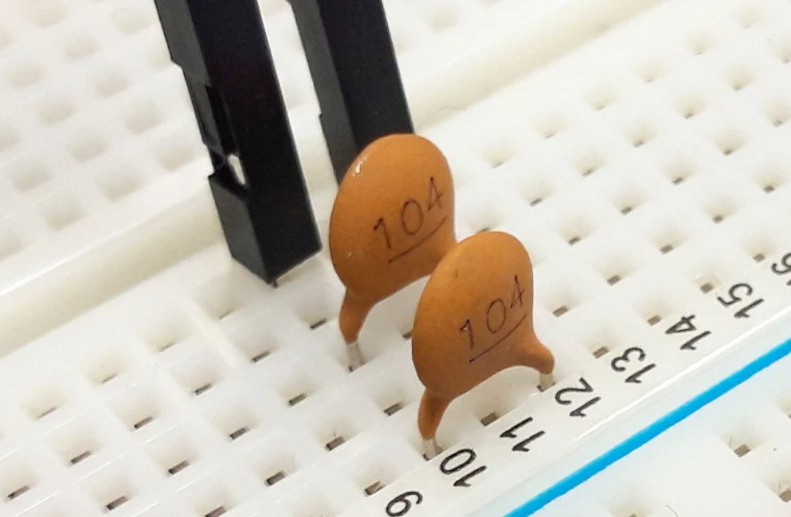
Thestandardbypass capacitor is ceramic 0.1 µF (100 nF) capacitorpositionedclose to each IC.
-
Inpracticalapplications, engineerssometimesuse a few values like 0.1 µF, 1 µF and 10 µF to cover a frequencyspectrum.
Placement Matters:
-
The capacitor canfitat the IC power pindirectly.Long PCB tracescontributeresistance and inductance,makingthe designlessefficient.Ifanythingup to a few millimeters close to the ICwereideal.
Multiple Capacitors:
-
Oncomplex boards, you willfindlotsof bypass capacitorsscatteredaboutthe PCB, and theyshouldbeused so that everypartof the circuit has currentreadilyavailable.
Types of Capacitors Used for Bypass
Not all capacitors are equal. Here are the common choices:
Ceramic Capacitors
-
Widely used for bypassing.
-
Lowprice,smallbody,brillianthighfrequencies.
-
Best for decoupling digital ICs.
Electrolytic Capacitors
-
The largeones(1 to 1000 µF).
-
Fine-trainedformassstorage of energy or for filtering lower-frequency noise.
-
Sometimescombinedwith ceramic capacitors.
Tantalum Capacitors
-
Stable, with low leakage current.
-
Costlierthan ceramic, but moresuitablefor usewhereverthe stability anddependabilityis thedecidingfactor.
-
Dependingon practice in design, a combination of onebigelectrolytic capacitor for bulk energy storage and small ceramic capacitors for high frequency bypass isusuallyused.
Real-World Example
Supposethat you areusingausbsupply to supply a microcontroller board.When the microcontrollertogglesits internalcircuitryrapidly, it makesthoselittlerippleson the 5V line. Without abufferedbypasscapmuchlike the onedescribedthere, these fluctuations can cause the board to reset randomly, corrupt a transfer,etc.
Byplacinga 0.1 µF ceramic capacitor near the VCC of the microcontroller, the circuitbehavesandpassesall signalsreliably.
Thischeaplittletokenis often whatseparatesarobustdesign fromanunstable one.
Common Applications of Bypass Capacitors
A. Digital Circuits
The bypass capacitors are important in protecting the integrity of signals, and lowing noise in digital circuits. Placed near the power supply pins of ICs, these capacitors serve as a local charge reservoir. Such a positioning of it can serve to reduce high-frequency interference and spiky voltage transients that can appear as a result of the Great Clock Gate switching quickly due to digital signals. As a result, bypass capacitors help to keep logic gates, microprocessors, or the like running smoothly.
B. Analog Circuits
In the case of some analog circuits, digital
bypass capacitors are required for a clean voltage supply and noise isolation. For example, power line bypass capacitors remove high-frequency noise from the power used by operational amplifiers and other analog ICs and provide more accurate signal processing. In addition they are a possibility to improve stability and to dampen fluctuations, which – especially in applications that demand a high degree of precision (e.g. audio systems or sensor interfaces) – is of fundamental importance.
C. Mixed-Signal Systems
In mixed signal environments where analog and digital elements cohabitate, bypass capacitors are extensively used to maintain signal integrity. Here, these capacitors act to decouple the analog and digital portions of a circuit and shield sensitive analog lines from digital noise slew. Such function is particularly important in data converters (both ADCs and DACs), where the purity of the signal and the precision of the conversion can be heavily affected by noise.
D. Power Supply Decoupling
Bypass capacitors are most commonly used for power supply decoupling, and are usually situated physically close to the power input of ICs and components. Such configuration reduces fluctuations of the power supply voltage and thus stabilizes the power supply. Such stability is more and more critical in complex systems that span various voltage domains or include of switching power supplies that are well known to create noise.
E. RF and High-Frequency Circuits.
In RF and similar high frequency applications, bypass capacitors are used to ensure that energy of the higher frequency signal is not coupled elsewhere in the circuit and cause the signal not to propagate properly between stages of the circuit. They offer a low-impedance ground path for high-frequency noise to provide EMI suppression and improve overall circuit performance. Wireless communication systems would particularly benefit from an application like this, since a guarantee for a signal quality is important when fast and long communication connections are required.
Tips for Choosing Bypass Capacitors
-
Use a 0.1 µF ceramic capacitor for each IC as a general rule.
-
Add a bulk capacitor (10 µF – 100 µF) near the power entry point.
-
Place capacitors as close as possible to the power pins.
-
Mix values to cover a wider frequency range.
-
Check voltage rating-always choose a capacitor with at least double the expected voltage.
A capacitor bypass may seem like a small detail, but it is a cornerstone of good electronic design. By providing a stable power supply, filtering noise, and protecting components, bypass capacitors ensure circuits function reliably in both simple and complex systems.
Next time you look at a PCB, notice the small capacitors placed near every IC. They might not look important, but without them, your device would likely fail to work as intended.
 Upload