A TVS (Transient Voltage Suppressor) diode is a fast, high-power protection device that clamps voltage spikes caused by ESD, EFT, inductive switching, and surge events. This guide explains how TVS diodes work, the difference between unidirectional and bidirectional devices, key datasheet parameters (VRWM/VBR/VC/IPP), and a practical selection checklist for power rails and high-speed signal lines.
A TVS diode is a specialized semiconductor designed to protect sensitive electronics from transient over-voltage. Under normal conditions it remains in a high-impedance (off) state. When a fast transient pushes the line beyond its threshold, the TVS enters avalanche breakdown and shunts current away from the protected circuit, limiting the voltage to a safer level.
Common protection targets include MCU/CPU I/O, ASICs, ADC inputs, USB/HDMI/Ethernet ports, industrial I/O, and DC power rails like 12V/24V/48V.
TVS protection can be understood as a "normally-off clamp." When the transient voltage rises quickly:
VRWM, TVS stays off (only leakage).
VBR, avalanche conduction starts.
VC, while the TVS diverts current to ground.
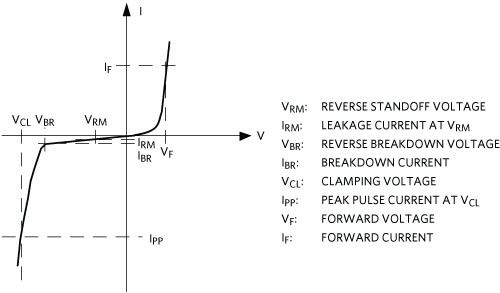
Selection core idea: Ensure VRWM is above your normal max voltage, and ensure VC stays below the damage threshold of the protected IC (considering layout inductance).
Unidirectional devices clamp primarily in the positive direction (and behave like a regular diode in reverse polarity). They are commonly used for DC power rails where polarity is known.


Bidirectional devices clamp in both directions and are well-suited to AC lines or signal interfaces that can see both positive and negative spikes (e.g., RS-485, CAN, audio lines).
| Type | Best for | Typical examples |
|---|---|---|
| Unidirectional | DC rails, battery inputs | 12V/24V input clamp, automotive rails |
| Bidirectional | AC/signal lines | RS-485/CAN, telecom, audio |
The maximum continuous voltage the TVS can tolerate while remaining off (only leakage). Choose VRWM ≥ maximum normal operating voltage (including tolerances).
The voltage at which the TVS begins avalanche conduction (measured at a small test current). VBR is not the final clamp voltage-it's the start of strong conduction.
The maximum voltage during a specified surge waveform/current. This is the most important value for IC safety. Lower VC generally means better protection, but it may increase leakage or capacitance depending on the part.
The maximum transient current the device can safely conduct under a given waveform (e.g., 8/20µs, 10/1000µs).
Peak transient power rating (commonly 400W/600W/1500W/3000W/5000W) under specific test conditions. Power rails and industrial environments often need higher ratings.
Critical for high-speed data lines. Choose low-capacitance TVS for USB 2.0/3.x, HDMI, Ethernet, LVDS, MIPI, etc., to reduce eye-diagram degradation and signal distortion.
| Parameter | Meaning | Why it matters |
|---|---|---|
| VRWM | Stand-off voltage | Must be above normal operating voltage |
| VBR | Breakdown start | Indicates conduction threshold region |
| VC | Clamping voltage | Directly impacts IC survival margin |
| IPP | Peak surge current | Must cover expected transient magnitude |
| Pppm | Peak transient power | Useful for power rail & surge robustness |
| Cj | Capacitance | Important for high-speed signal integrity |

Set VRWM above the maximum expected steady-state voltage, including tolerance, ripple, and worst-case conditions.
Ensure the TVS clamping voltage VC (at the relevant surge current waveform) remains below the protected IC's absolute maximum voltage rating (with margin). Consider PCB trace inductance which can increase peak voltage.
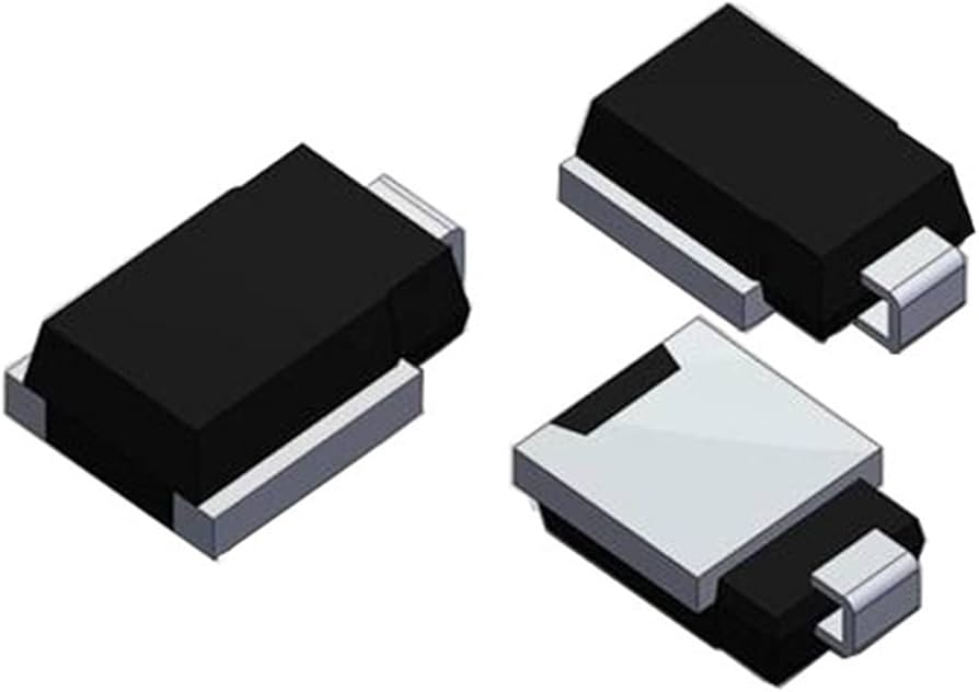
For power rails, packages like SMA/SMB/SMC are common. For data lines, DFN/SOD low-cap arrays are typical. Higher power generally needs larger packages and more copper area.
If your circuit is battery-powered or precision analog, leakage matters. If it's high-speed, capacitance matters.
SMAJ (≈400W), SMBJ (≈600W), SMCJ (≈1500W).
Actual ratings depend on manufacturer and waveform-always confirm the datasheet.

| Device | Best for | Pros | Cons |
|---|---|---|---|
| TVS diode | ESD/EFT/Surge clamping | Fast response, high surge capability, predictable | Capacitance/leakage tradeoff, needs good layout |
| Zener diode | Voltage regulation/reference | Simple, low cost | Not designed for high-energy transients |
| MOV | High-energy AC mains surge | High energy absorption | Aging over time, slower, higher leakage |
TVS diodes must be connected in parallel with the line being protected, so they can shunt surge current to ground.
It can. For high-speed interfaces you should use low-capacitance TVS devices and place them close to the connector with minimal stubs.
Yes. Under extreme surge conditions, a TVS diode may fail short as a protective "sacrifice," which can save the downstream circuit.
Pick VRWM slightly above your maximum normal line voltage (including tolerance/ripple). Then verify VC stays within your IC's safe limits.