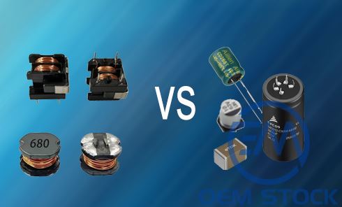
Capacitor Vs Inductor: Key Differences, Functions & Applications
Capacitors and inductors are two essential passive components used in almost every electronic circuit-from power supplies and filters to radios and smartphones. Although they both store energy, they do so in fundamentally different ways. Understanding how each component works and how they interact is critical for designing efficient and stable circuits.
What Is a Capacitor?
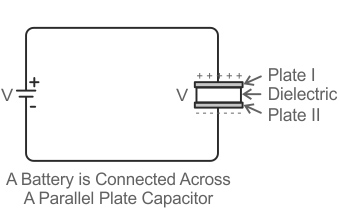
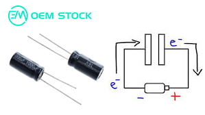
A capacitor is a passive two-terminal electrical component that stores energy in an electric field. It consists of two conductive plates separated by an insulating material called a dielectric (such as ceramic, plastic, or aluminum oxide). When a voltage is applied across the plates, opposite charges accumulate on each plate-creating a potential difference and storing electrical energy.
How a Capacitor Works
When connected to a voltage source, one plate becomes positively charged while the other becomes negatively charged. The dielectric prevents current from flowing directly between the plates but allows the capacitor to store charge. When the voltage source is removed, the stored charge can be released back into the circuit.
The ability of a capacitor to store charge is called capacitance (C), measured in farads (F). The capacitance depends on three main factors:
- The surface area of the plates (larger area → higher capacitance)
- The distance between the plates (smaller distance → higher capacitance)
- The dielectric constant of the material (higher constant → higher capacitance)
Capacitance Formula
The basic equation for a parallel-plate capacitor is:
C = ε × (A / d)
- C = capacitance in farads (F)
- ε = permittivity of the dielectric material
- A = plate area (m²)
- d = distance between plates (m)
Energy Stored in a Capacitor
The energy stored in a capacitor is given by:
E = ½ × C × V²
where V is the voltage across the plates. This stored energy is released when the capacitor discharges into the circuit.
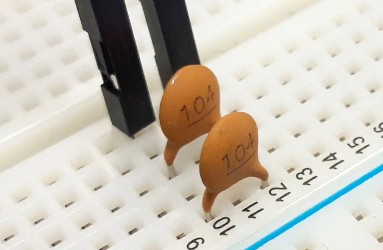
Types of Capacitors
- Ceramic Capacitors: Small, low-cost, used in signal and decoupling circuits.
- Electrolytic Capacitors: Large capacitance, polarized, used for power filtering.
- Film Capacitors: Excellent stability and long life, used in audio and precision circuits.
- Tantalum Capacitors: High capacitance per volume, used in compact electronics.
- Supercapacitors: Very high energy storage, used for short-term power backup.
Functions of a Capacitor
- Stores electrical energy temporarily.
- Blocks DC current while allowing AC signals to pass (coupling).
- Smooths voltage fluctuations in power supplies (filtering).
- Sets timing intervals in oscillators and RC circuits.
- Stabilizes voltage and power factor in AC systems.
What Is an Inductor?
An inductor is another passive two-terminal component, but it stores energy in a magnetic field created by the flow of electric current through a coil of wire. Inductors oppose changes in current due to the property of inductance (L), measured in henrys (H).

How an Inductor Works
When current flows through a coil, a magnetic field forms around it. If the current changes, the magnetic field also changes, inducing an electromotive force (EMF) that opposes the change in current (according to Lenz's Law). This makes inductors ideal for filtering, energy transfer, and controlling transient current spikes.

Inductance Formula
The inductance of a coil is determined by:
L = (μ × N² × A) / l
- L = inductance in henrys (H)
- μ = permeability of the core material
- N = number of turns of the coil
- A = cross-sectional area of the core
- l = length of the magnetic path
Energy Stored in an Inductor
The energy stored in an inductor is:
E = ½ × L × I²
where I is the current through the coil. The magnetic field collapses when the current decreases, releasing this energy back into the circuit.
Types of Inductors
- Air-core Inductor: No magnetic core; suitable for high-frequency circuits.
- Iron-core Inductor: High inductance; used in power transformers.
- Ferrite-core Inductor: Common in RF and switching power supplies.
- Toroidal Inductor: Donut-shaped core for compact, low-loss designs.
Functions of an Inductor
- Stores energy in a magnetic field.
- Opposes sudden changes in current (acts as a choke).
- Filters out high-frequency noise in power circuits.
- Transfers energy in transformers and converters.
- Creates resonance with capacitors in tuning circuits.
Key Differences Between Inductor and Capacitor
| Property | Capacitor | Inductor |
|---|---|---|
| Energy Storage | Electric field | Magnetic field |
| Reactance Relation | Decreases with frequency (Xc = 1/2πfC) | Increases with frequency (Xl = 2πfL) |
| Behavior in DC | Open circuit after charging | Short circuit after steady current |
| Phase Relationship | Current leads voltage by 90° | Current lags voltage by 90° |
| Energy Formula | E = ½CV² | E = ½LI² |
| Main Function | Blocks DC, smooths voltage | Blocks AC, smooths current |
| Symbol Unit | Farads (F) | Henrys (H) |
| Typical Usage | Timing, filtering, coupling | Filtering, energy storage, transformers |
Behavior in AC and DC Circuits
In DC Circuits
- Capacitor: Allows current flow only during charging, then blocks DC completely.
- Inductor: Initially resists current, but after steady state acts as a simple wire (low resistance path).
In AC Circuits
- Capacitor: Offers less opposition to higher frequencies, making it ideal for high-pass filters.
- Inductor: Offers more opposition to higher frequencies, making it ideal for low-pass filters and chokes.
Together, they form LC circuits that can resonate at a specific frequency f = 1 / (2π√(LC)), used in radio tuning, oscillators, and signal filters.
Applications of Inductors and Capacitors
Common Capacitor Applications
- Voltage smoothing in DC power supplies.
- Coupling and decoupling in amplifiers and signal lines.
- Timing in oscillators, pulse circuits, and delay generators.
- Energy storage for power stabilization and UPS systems.
- Noise filtering and EMI suppression.
Common Inductor Applications
- Chokes and filters in power converters.
- Energy transfer in transformers and converters.
- Current smoothing in switching regulators.
- RF tuning and impedance matching.
- Magnetic energy storage and surge suppression.
Frequently Asked Questions (FAQ)
1. Which stores more energy: a capacitor or an inductor?
It depends on voltage and current levels. Capacitors store energy efficiently at high voltages, while inductors are better for large current handling in magnetic fields.
2. Why do inductors block AC but capacitors pass AC?
Inductors' reactance increases with frequency, opposing fast-changing currents. Capacitors' reactance decreases with frequency, allowing AC to flow more easily.
3. Can inductors and capacitors be used together?
Yes. Together they form LC circuits that determine resonant frequency, useful in filters, oscillators, and communication circuits.
4. What happens if we swap an inductor for a capacitor?
The circuit's phase response reverses. For example, an RC low-pass filter becomes a high-pass if replaced with an RL combination, changing how signals are filtered.
5. How do capacitors and inductors affect phase in AC?
Capacitors cause current to lead voltage by 90°, while inductors cause current to lag voltage by 90°, creating phase shift used in power factor correction and AC control.

Related information
- 2025.10.28 Choosing the Right LED Resistor for 12V LEDs