Silicon PICS capacitors (Passive Integrated Components on Silicon) are advanced thin-film capacitors fabricated on silicon wafers using semiconductor manufacturing techniques. Unlike traditional ceramic or electrolytic capacitors, PICS capacitors integrate dielectric and electrode layers on silicon substrates, providing exceptional precision, stability, and miniaturization.
They are sometimes referred to as silicon integrated capacitors or IPD capacitors (Integrated Passive Devices). Their construction ensures extremely low ESR and ESL, making them ideal for high-frequency, RF, and power integrity applications.
IPDiA high stability capacitors are dedicated to all demanding applications where stability is the main parameter. IPDiA Silicon capacitors offer improved temperature, voltage, and aging performance as well as high reliability far exceeding the alternative capacitor technology. Silicon capacitors offer intrinsic performances which can improve the applications performances when they replace ceramic/tantalum capacitors. They are also a smart way to reduce the application volume and increase the IP protection level.
|
Problematic with SMD capacitors |
Solutions and benefits with PICS |
|
High leakage current for battery powered applications. |
Very low leakage current (<500pA fora capacitor 200nF capacitor @3.6V) guaranteed by process. No screening required. |
|
Reliability (cracks on MLCC...). |
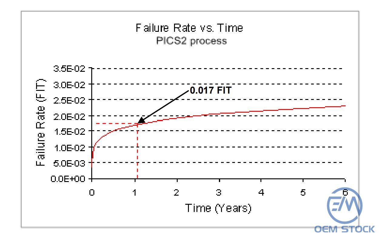
High integration capability reducing the number of passive components in the application and reducing component interconnects. TDDB>10 years @100°C >12 years @37°C. |
|
Decoupling efficiency requiring (RF, digital). |
Very low ESL capacitors. Capacitance to be used can be optimized. |
|
Efficient decoupling with minimum embedded capacitors. |
Very low ESL capacitors. |
|
Over sizing of capacitor value (often a factor of 2) for sensitive capacitive circuitry to secure the amount of energy stored in the capacitors, whatever the operating voltage. |
Very stable capacitor value over the full operating voltage & temperature ranges. |
|
Size. |
Integration with a volume of2200nF/mm3 |
|
Voltage and temperature stability. |
Ultra stable capacitors in the range -50 to +200°C and 0 to +5.5V. |
The PICS technology offers clear advantages compared to MLCC and Tantalum capacitors.
The temperature performances exceed MLCC and Tantalum capacitors, as depicted in the next figure.
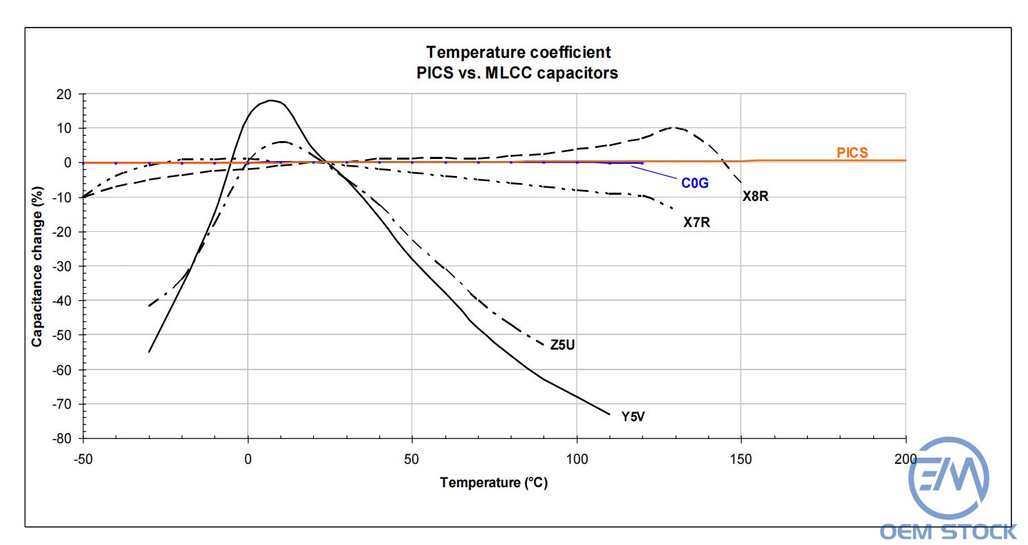
Fig.1 Temperature performances comparison with various types of MLCC capacitors
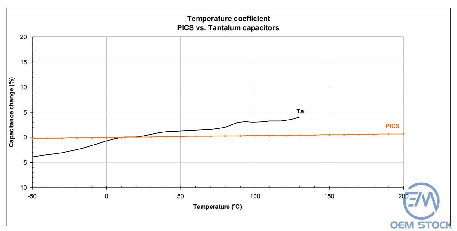
Fig.2 Temperature performances comparison with Tantalum capacitors
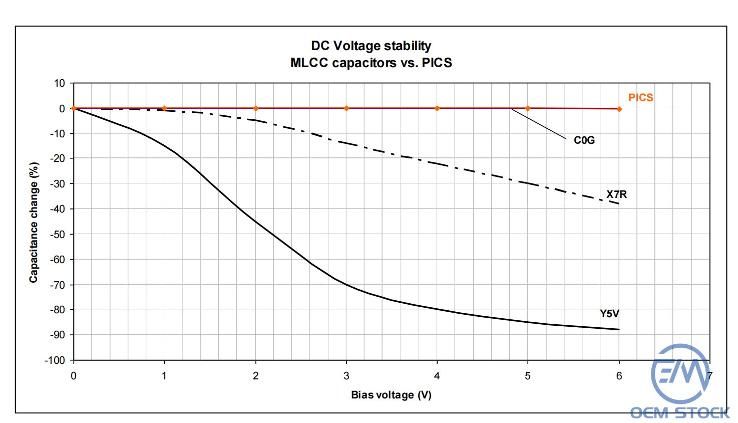
Fig.3 Voltage stability performances comparisons with various type of MLCC capacitors
Because of their 3D structure, the silicon capacitors offer major improvements in terms of parasitics compared to commonly used capacitors. Fig.4 shows the general electrical model of a capacitor
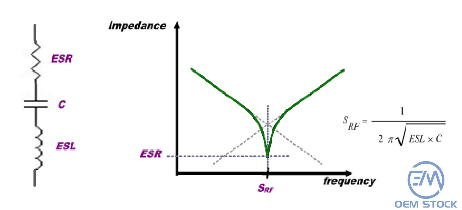
Fig.4 Capacitor model and Series Resonance Frequency definition
Both ESR and ESL are lowered compared to MLCC and Tantalum capacitors for the same capacitance value, having a direct impact on the applications performances.
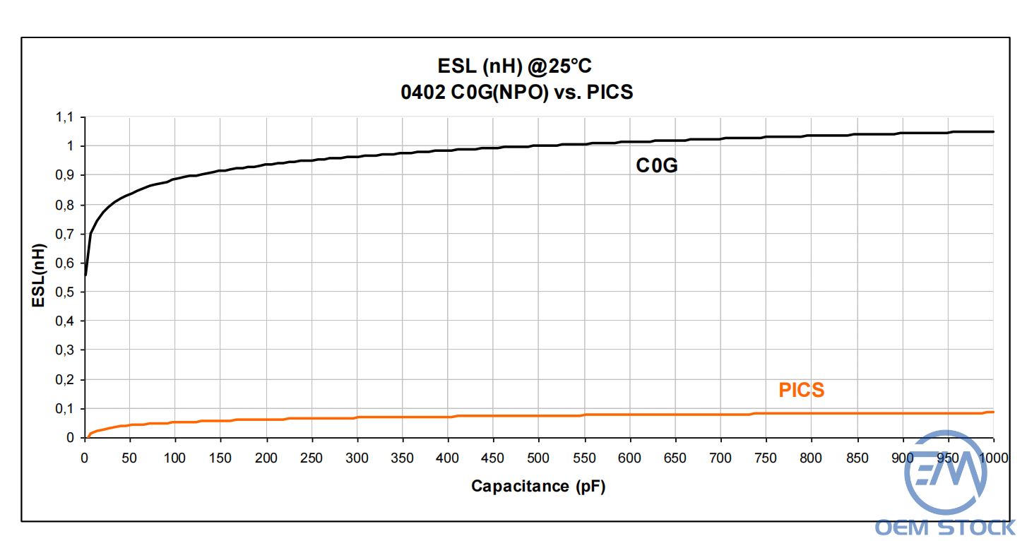
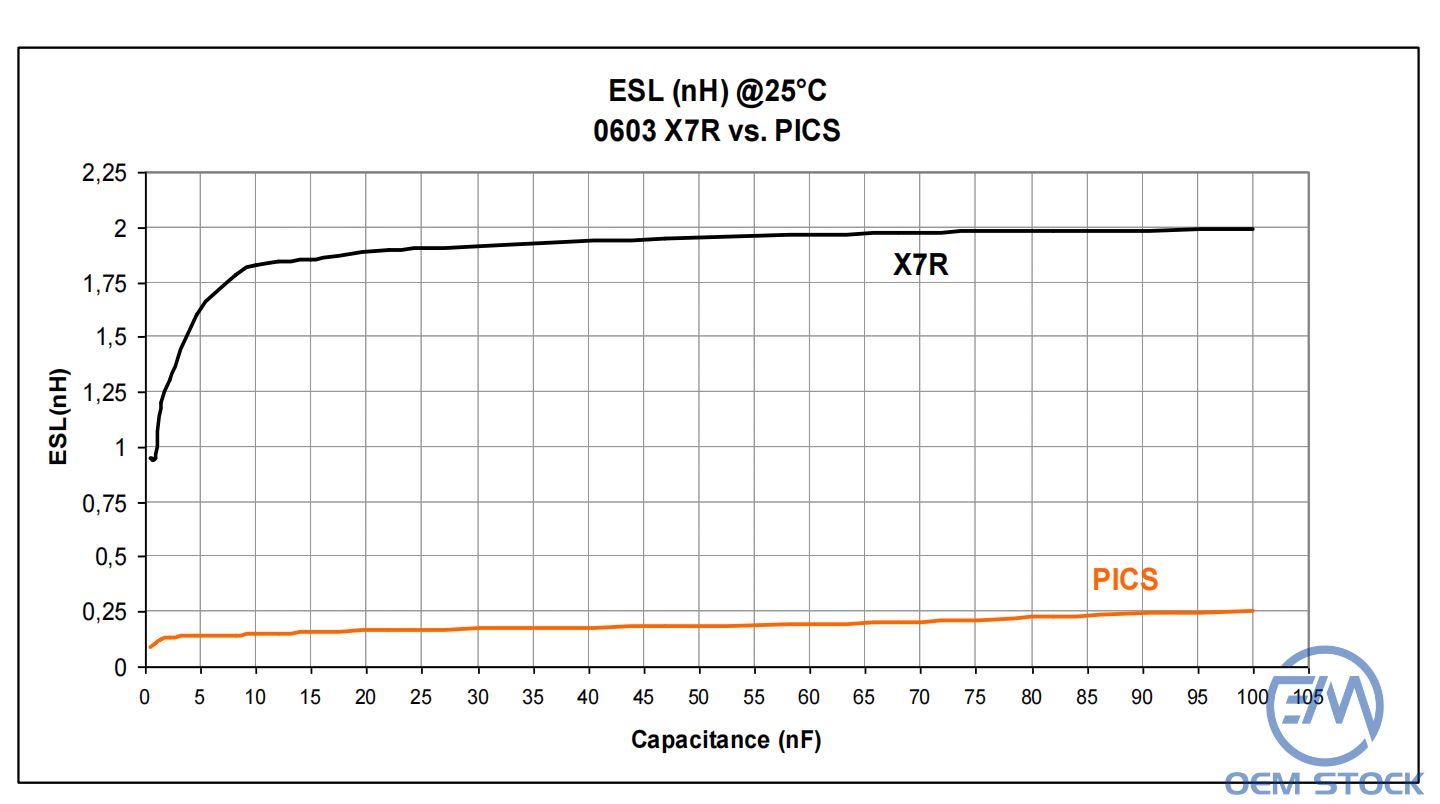
Fig.6 Comparison between 0603 X7R and PICS capacitors
The power supply decoupling can often be optimized with even better performances compared to standard decoupling with SMD capacitors but a few rules need to be verified.
A decoupling capacitor offers two domains where the decoupling is effective:
The next figure represents the comparison in terms of insertion loss between a 100nF SMD X7R capacitor and a 100nF PICS capacitor.
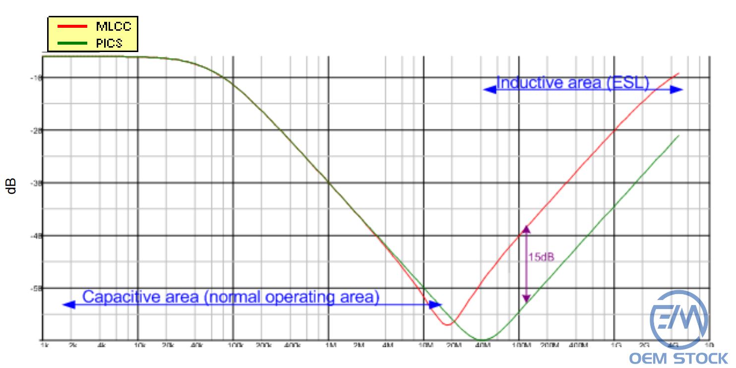
The insertion loss at the resonance frequency is directly driven by the capacitor ESR (lower with PICS technology). The decoupling efficiency can be improved by 15dB in the inductive area.
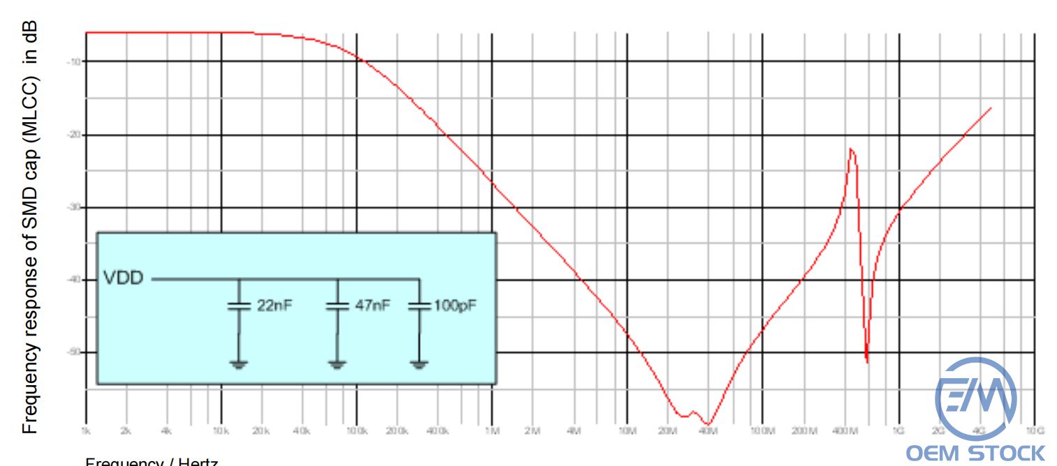
Fig.8 Analog decoupling situation with SMD capacitors (MLCC)
For such a situation, the decoupling capacitors value needs as a first order to stay at the same value (no optimization). The advantage with PICS is a better efficiency at the resonance frequencies (lower ESR).

Fig.9 Analog decoupling situation with PICS capacitors
Note that the PICS technology allows fine tuning of the ESL to place the notches at the required frequencies.
This situation is met with decoupling of digital devices. As example, we assume a 100nF capacitor is used for the decoupling and most of the time, the capacitor is used in the inductive area as we need to suppress frequencies higher than a certain value. The PICS capacitor is placed very close to the power supply pins/pads to be decoupled, reducing in a drastic way the parasitic inductance between the capacitor and the pads. It is very common to divide the SMD capacitor value by a factor 4 to 5.
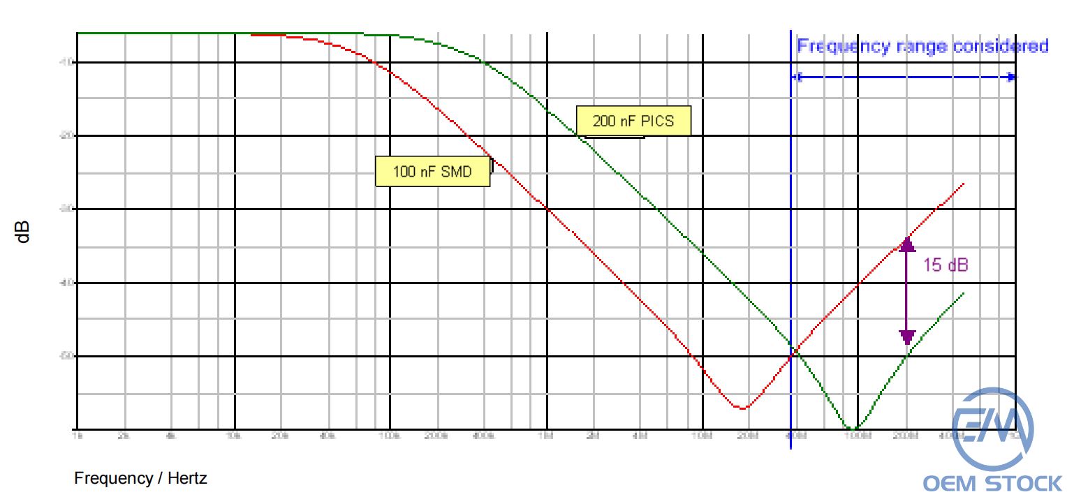
Fig.10 Digital power supply decoupling situation with PICS capacitors
In charge pump applications, two parameters are critical:
The next figure shows the stability of the capacitor value (C) compared to the value when no voltage is applied (C0) for various supply voltages and temperatures.

Fig.11 Capacitance stability vs. applied voltage at different temperatures
The capacitance value 'C' can be expressed as:
C=C0.(1+VC1.V +VC2 .V2 ).(1+ Tcl.(T-T0 ))
For PICS3:
VC1= 1100ppm/V
VC2=-300ppm/V²
Tcl= 62ppm/K
The next figure provides some indications in terms of leakage current performances for three capacitor values processed in PICS3.
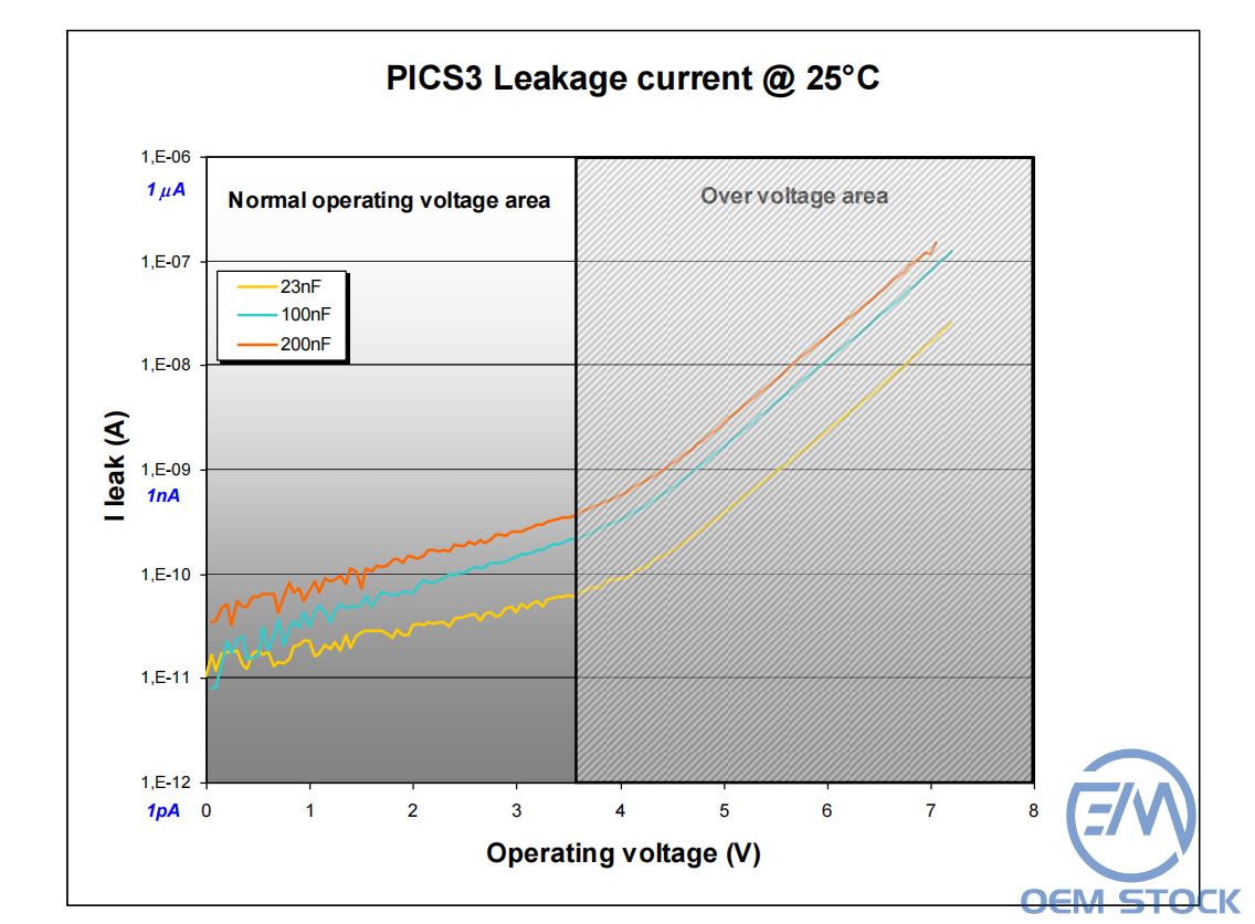
The next figure provides the leakage current variation for a 100nF capacitor vs. the operating voltage for different temperatures.
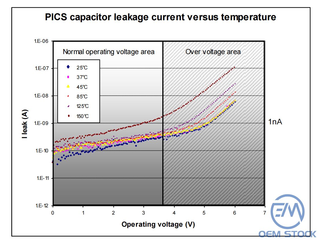
Fig.13 Leakage current in a 100nF PICS capacitors vs. temperature (PICS3)
Key values:
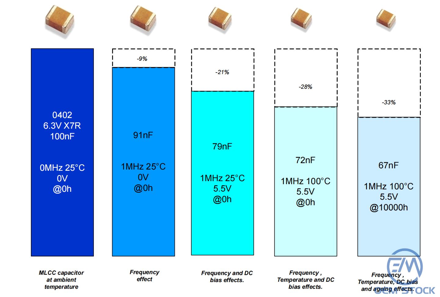
In many applications, the capacitors value is oversized to take into account that the capacitance changes with the operating voltage, with the temperature and ageing.
As an example, we assume a 100nF 0402 X7R 6.3V capacitor in an application working at 100°C, under a 5.5V DC operating voltage and achieving filtering of a signal @1MHz. The 100nF capacitors represent a standard value in many applications.
The PICS capacitor optimized value would be in the range of 65nF, because of the capacitor stability over voltage, temperature and ageing, which is about 35% lower than the SMD value (see next figure).
PICS IPD technology is a silicon based process, allowing various assembly architectures:
Dies can be molded (plastic compound, glass), used as chip on board, flip-chip on PCB or flex substrate.
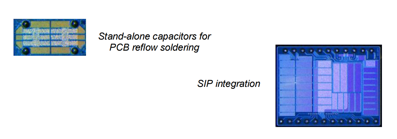
Fig.16 Various integration possibilities with the capacitors in PICS technology
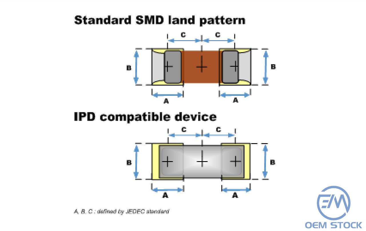
Fig.17 Stand-alone PICS capacitors with SMD compatible footprint
IPDiA is RoHS compliant.
|
|
MLCC/Tantalum |
PICS |
|
Temperature stability |
-- |
++ |
|
Voltage stability |
- |
++ |
|
Leakage current |
- |
++ |
|
Reliability |
-- |
+++ |
|
Integration |
+ |
+++ |
|
Decoupling efficiency |
+ |
+++ |
|
Flexibity with values |
E6, E12 …series |
customized |
 Upload